
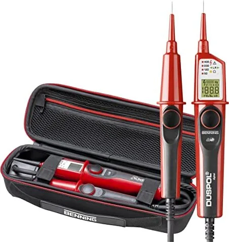
Benning DUSPOL digital Bruksanvisning
PDF-manual · 91 Sidor
Svenska



Snabbkontroll
Felaktigt svar, försök igen.
Chatta med din Benning DUSPOL digital-manual med hjälp av AI
Få omedelbara AI-svar från din Benning DUSPOL digital-manual
Fråga vad som helst om Benning DUSPOL digital. Svaren kommer från denna bruksanvisning, med de sidor de bygger på.
DUSPOL digital Underhallsschema
Byt de två Micro LR03/AAA-batterierna så snart symbolen för urladdat batteri visas på LC-skärmen.
Kontrollera att spänningsprovaren fungerar korrekt omedelbart före och efter användning för att säkerställa säkerheten.
Om enheten lagras under en längre tid, ta ur batterierna ur enheten för att förhindra skador.
Rengör utsidan av enheten och eventuella föroreningar i batteriområdet med en ren, torr trasa.
Ställ en Fråga
Rekommenderar du DUSPOL digital?
Ja Nej
Jaleel Marquardt
för 6 månader sedan
Varför var batterierna redan installerade i förpackningen när jag fick varan?
Vanliga frågor
Utför en funktionskontroll genom att kortsluta sondspetsarna och hålla ned knappen i tre sekunder. Högtalaren ska ljuda och alla LED-lampor och displaysegment måste lysa upp. Du bör också testa den på en känd spänningskälla som ett 230 V-uttag.
Är detta svar till hjälp?
Ja, genom att kortsluta sonderna och trycka på knappen tre gånger tills Lo U visas. Detta aktiverar ett lågspänningsläge som möjliggör mätningar från 1,0 V till 11,9 V, även om frekvensindikering är inaktiverad i detta läge.
Är detta svar till hjälp?
Vibrationsmotorn hjälper till att skilja mellan driftspänning och störningsspänningar. Genom att aktivera båda knapparna växlar du till ett läge med låg intern resistans som dämpar reaktiva spänningar och urladdar kondensatorer.
Är detta svar till hjälp?
Leta upp batterirummet på baksidan av displayhandtaget. Skruva loss locket, ta bort de gamla AAA-batterierna, sätt i två nya och se till att polningen är korrekt, och skruva sedan tillbaka locket ordentligt.
Är detta svar till hjälp?
Den har en IP65-klassning, vilket innebär att den är dammtät och skyddad mot vattenstrålar. Den kan användas i regn, men får inte nedsänkas i vatten.
Är detta svar till hjälp?
Om spänningen överstiger 1 050 V AC eller 1 250 V DC visar displayen OL och alla stegindikator-LED:n blinkar för att varna för överbelastning.
Är detta svar till hjälp?
Fördelar och Nackdelar
Fördelar

- Skiljer mellan driftspänning och störningsspänningar med hjälp av lastanslutning och vibrationsmotor
- Omfattande testmöjligheter inklusive kontinuitet, resistans, diod och kabelbrottsdetektering
- Hög säkerhetsklassning med IP65-skydd mot damm och vattenstrålar för användning i hårda miljöer
- Automatisk självtestfunktion säkerställer att alla komponenter som LED och högtalare fungerar korrekt innan användning
- Tvåhandsdesign med isolerade grepp säkerställer säker hantering vid testning av livande kretsar
Nackdelar

- Kräver en minsta spänning på 9 V för att aktiveras, vilket begränsar användning på mycket låga kraftkällor utan särskilt läge
- Batteritiden kan minska vid förlängda belastningstester på grund av hög strömdrag från vibrationsmotorn
- Fassekvensindikering fungerar endast i jordade nätverk vid 50/60 Hz, vilket begränsar global tillämplighet
- Kan inte användas med batterirummet öppet, vilket kräver noggrann hantering av strömtillgång
- Maximal arbetscykel är begränsad till 30 sekunder för att förhindra överhettning, vilket kräver pauser under förlängd testning
Produkt Specifikation
Mätomfång
1-1000 V
Produkt Beskrivning
Benning Digital Volttester med väska - Essentiell säkerhet för professionella
Benning Digital Volttester med väska är ett robust och pålitligt verktyg designat för kvalificerade elektriker som kräver precision och säkerhet i sitt dagliga arbete. Denna enhet, känd som DUSPOL digital, representerar en betydande framsteg inom elektrisk testutrustning genom att kombinera flera diagnostiska funktioner i en enda ergonomisk enhet. Oavsett om du kontrollerar frånvaro av spänning, tester fassekvenser eller söker efter kabelbrott, ger denna tester tydlig visuell och auditiv feedback för att säkerställa din säkerhet.
Utstyrd med en intuitiv LC-display och en flerlags LED-indikator ger testern omedelbara insikter i den elektriska miljön. Den kan mäta växelström upp till 1 000 V och likström upp till 1 200 V med hög noggrannhet. Inkluderingen av en vibrationsmotor gör det möjligt för användare att skilja mellan driftspänning och störningsspänningar, en kritisk funktion när man hanterar komplexa installationer där strömslingor kan ge falska avläsningar. Enheten slås automatiskt på när den upptäcker en spänning på minst 9 V, vilket säkerställer att du inte blir överraskad under en inspektion.
Designad med användarsäkerhet som topprioritet har testern isolerade handtag och kräver en specifik två-polig test för att bekräfta spänningsfrånvaro, i enlighet med strikta säkerhetsstandarder som DIN EN 61243-3. Den inbyggda självtestfunktionen verifierar integriteten hos högtalaren, LED:erna och displayen innan varje användning, vilket ger dig förtroende för dina resultat. Dessutom möjliggör lägesläget för lågspänning exakta mätningar ner till 1,0 V, vilket gör det mångsidigt för olika applikationer utöver vanliga nätspänningskontroller.
Paketet inkluderar en hållbar transportväska som skyddar instrumentet mot damm, fukt och fysisk skada under transport. Med sin IP65-klassning är testern motståndskraftig mot vattenstrålar och damm, vilket gör den lämplig för användning i hårda industriella miljöer eller utomhusförhållanden. Regelbunden underhåll är enkelt, involverar bara en torr trasa för rengöring och tidig batteribyte med standard AAA-celler. För professionella som söker en omfattande lösning för elektrisk diagnostik står Benning Digital Volttester med väska ut som en pålitlig följeslagare som kombinerar funktionalitet, hållbarhet och säkerhet.
Sök efter 67 706 Manualer online


Ange märke eller modell
Dan King
för 4 månader sedan
Är kalibreringstjänsten nödvändig för denna enhet, eller kan jag hoppa över den?
Manual.ly
för 4 månader sedan
Baserat på användarfeedback krävs inte kalibreringstjänsten. Enheten utför sin avsedda funktion korrekt direkt ur lådan utan ytterligare kalibreringssteg.